|
|
|
Who's Online
There currently are 6043 guests online. |
|
Categories
|
|
Information
|
|
Featured Product
|
|
|
 |
|
|
There are currently no product reviews.
 ;
perfect copy, im very satisfied, i was need the diagram over the powersupply and
the copy was very sharp
;
This is exactly the service manual I needed.
Complete with all schematics, partslists, PCB layouts and alignment instructions.
This manual covers both the T-4970 en T-488F Onkyo tuner.
 ;
IF PRINTED CIRQUIT BOARD WIRING VIEW WAS ONE TONE LIGHTER, THEN 5 STAR RANK HAS TO BE MY CHOISE.
;
Very usefull, good quality drawings !
Muito útil encontrei todas as informações necessárias.
;
Wanting to repair a neighbours tape recorder I needed the necessary information, it makes it easier. Although the service manual is described as "Language : English" To my dismay I found that it is entirely written in German, a language I do not understand. At least I now have the schematics which will help of sorts. I may not use this service again due to the laguage difficulty after all when it states English you do not expect it to be entirely in another language.
Alignment and Adjustment
WHITE ( APPROX. 100% ) APPROX. 0.7V APPROX. 0.3V H
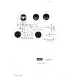
2-12. Y-FM Deviation (Hi8) : This adjustment sets the Y_FM modulation
1.0 0.02Vp-p
level in recording. For adjustment, playback the self-recorded signal and observe the VIDEO OUT signal. Note : It is a little difficult to adjust because you can check the waveform in playback mode even though the adjustment is performed in VCR record mode. So you have to do it carefully. a. Preparations
TAPE EQUIPMENT HI-8 TAPE FOR RECORDING OSCILLOSCOPE NONE CN452 PIN13 OD Y-FM DEVIAT (HI8)
l. Be sure to press the �PROGRAM AE(CONFIRM)� button on FUNCTION to memorize setting. m. Reset the power source so as to fix the new data to the camcorder�s EEPROM.2-11. Y-FM Carrier (Hi8)
2-11. Y-FM Carrier (Hi8) : This adjustment is performed to set the synctip level of the composite video signal. Maladjusted Y-FM carrier impact to the playback picture, there may be black or white dot noise. a. Preparations
TAPE EQUIPMENT OTHER TEST POINT ADDRESS NAME HI8 TAPE FOR RECORDING FREQUENCY COUNTER NONE IC 201 PIN 13 OC Y-FM CARRIER (HI-8)
OTHER TEST POINT ADDRESS NAME
b. Connect a power source. c. Get into the VCR adjustment mode. d. Press the �FADE(MODE UP)� or �BLC(MODE DOWN)� button of FUNCTION so as to select the address OD. e. Insert a Hi-8 Tape to the camcorder. f. Press the �START/STOP� button on the Rear board so as to set the camcorder to RECORDING mode. g. Record for enough time to check the waveform when you playback where you recorded in step f). * 1 minute may be enough to check the waveform in playback mode. i. Make sure that the waveform is to be as below. (If OK, go to step l). j. In case of the waveform level is bigger than 1Vp-p, press the Data Down button so as to set to down the waveform level and if the waveform level smaller than 1Vp-p, press the Data Up button so as to set to up the waveform level.
WHITE ( APPROX. 100% ) APPROX. 0.7V APPROX. 0.3V H 1.0 0.02Vp-p
b. Connect a power source. c. Get into the VCR adjustment mode. d. Press the �FADE(MODE UP)� or �BLC(MODE DOWN)� button of FUNCTION so as to select the address OC. e. Insert aHi-8 Tape to the camcorder. f. Press the �START/STOP� button on the Rear board so as to set the camcorder to RECORDING mode. g. Connect the frequency counter to the addressed Test Point. h. Press the �TITLE(DATA DOWN)/DSE(DATA UP)� button so as to set the frequency to 5.99MHz ±0.02MHz i. Be sure to press the �P.AE(CONFIRM)� button on FUNCTION to memorize setting. j. Reset the power source so as to fix the new data to the camcorder�s EEPROM.
Samsung Electronics
4-47
|
|
|
> |
|